The VX-7 and other Yaesu VX series are noted for low microphone audio.
It is generally a bad idea to blindly increase the deviation through the service menu.
If maximium deviation is set beyond 5kHz total, “talk-off” may be experienced for loud audio through the repeater/receiving radio.
The transmit bandwidth becomes excessive and falsely closes the repeater squelch on loud audio.
I had read that piercing the microphone diaphragm (on the front cover, NOT on the mic element itself!) would improve the microphone sensitivity.
I pierced the thin diaphragm, and noted increased microphone sensitivity.
Wind noise is frequently a problem in internal mics, and it did raise this issue slightly.
However, I now can talk about 12 cm from the microphone in most cases and be well heard–before it was more like 4 cm from the microphone!
Of course, I left the TX deviation adjustment as from the factory.
You should keep in mind that you are now inviting dust and water into the microphone element.
I plan to put a small piece of Motorola speaker felt into the cavity, to prevent most impurities from entering.
I would not recommend just leaving the hole open.
I was pleasantly surprised upon some informal empirical testing with the Maldol MH-209SMA vs. the SMA503.
The SMA503 has about 18 cm of radiating length while the MH-209SMA appears to have only about 5 cm.
When used in conjunction with the Yaesu MH-57 speaker-mic, about 2cm of the 5cm is blocked.
As compared to an SMA503 with no speaker-mic, the loss seems to be no worse than 5 dB or so (both receive and transmit).
This is true on both 2 meters and 440.
I didn’t test it on 6 m or 220 MHz, because the SMA503 is not rated for those bands.
Shortwave and MW band performance is much BETTER with the MH-209 than with the SMA503, which seems counterintuitive unless you consider that the feedpoint method of the SMA503 may be presenting a very bad impedance far from the desired bands.
FM broadcast was a little worse, but very usable.
800 MHz seemed a little worse too.
The antenna is very flexible and seems like it won’t be prone to the breakage and kinking the SMA503 is known for.
I would recommend the MH-209 antenna to people where range is not the overriding concern, but who need small size while maintaining adequate performance.
The Yaesu VX-7, while overall an excellent amateur transceiver, suffers from a problem it shares with certain commercial handheld radios, that is of losing receive audio intermittently.
The loss of audio stems from the flexible tensioned metal tangs that make contact to tin patches on the VX-7 internal speaker.
I bent the speaker tension tangs outward resulting in about 1.5 mm more outward protrusion, thus reenacting a secure connection to the internal speaker.
Overbending these tangs could cause them to break, or worse, weaken them so they break later, shorting out internal components of the VX-7.
I recommend you take this radio to a qualified repairperson to perform this repair.
It appears the VX-7 speaker model number is “Pryme 32N-A9906”; 8 Ω, 0.5 W
Nextel iDEN tethering to a laptop phone connection was at about 10 kbps speeds.
Less than the average home 30-40 kbps modem connection but not much worse considering the wide Nextel coverage area.
Typical bandwidth is 0.5-1 Mbps depending on the time of day.
Dynamic browser sensing for three tiers of content presentation for mobile/desktop web could work like:
Essential mobile 2G Java browsing: 2-3 small images max, simple table, list.
Full mobile: For Blackberry / Opera class browsers on 3G. 3-4 small images, pretty table, list, forms. HTML+CSS+images < 150kB ~ 6 seconds render time.
Full desktop: often not rendered properly on the mobile browser.
Heavily loaded LTR trunked radio systems with too many users homed on the same repeater may have a problem with radios randomly failing to transmit.
Monitoring for LTR trunked radio system overloading may be viewable via controller statistics.
With LTR if too many groups are homed on one repeater, the chance of two people keying up before the repeater can make its first response goes up.
Then, either neither party can transmit if the overlap is early (no clear-to-talk), or both will transmit.
In the first case, out-of-range tone is given.
In the second case, clear to talk is given but the transmissions are uselessly garbled (or maybe, one signal dominates).
Solving LTR trunked radio system overloading involves reprogramming every radio in the system, so plan first.
Distribute home channels for different groups that talk at the same time.
If the system needs an “all call”, have a small dispatch console that can key multiple radios simultaneously–if not, you’ll need to implement one.
This solution is fairly unique to LTR.
To detect the amount of “desense”, that is, how many dB receiver sensitivity is degraded when connected to the antenna from its own or other transmitters, and trace the desense source, a signal generator with an “isotee” is used to generate a precise signal level with a dummy load and antenna.
The test is accomplished in two parts–first determine sensitivity loss the system has by ambient antenna system noise.
connect the dummy load, then note the SINAD level achieved for a given signal level (typically values of 10 to 15 dB would be used).
the antenna system is connected, and the signal generator RF output level is raised until the SINAD reading matches that with the dummy load. The difference between the two signal generator level in dB represents the loss of sensitivity caused by ambient site noise.
the test is repeated, but this time transmitting while measuring SINAD (if the device under test is a repeater or full-duplex device). The increase in signal generator level over that required to overcome ambient noise is the amount of desense created by the transmitter.
It desense is observed with only the dummy load, assuming the dummy load and test cables present a good impedance and are well shielded, then suspect the duplexer is mistuned, or there is a cabling/connection problem.
If no desense with the dummy load, then proceed to test the antenna system.
If a rise on the antenna system only suspect bad connections or lightning protector that’s gone bad, or a bad antenna (cheap model or oxidized to create IM products).
Expected repeater dense measurements: ideally there would be no site noise (rather, site noise below the thermal noise floor set by cabling).
This is usually not the case, especially for VHF.
Expect to see some single digit dB degradation due to site noise on VHF, hopefully less than 3dB on UHF and above.
Isotee repeater desense connection
In terms of desense caused by the repeater, it should be below detectable levels.
Only in cases where the so-called “flat-pack” notch-only duplexers should there be detectable levels of desense from the duplexer.
With flat-packs it should be 1dB or less.
If using band-pass/band-reject duplexers with quality RG-142 cable and N-connectors, there should be no desense to the 100 Watt+ output level.
An examples 450 MHz repeater desense measurement was the repeater desensing itself 6-10dB.
The level varies and sometimes is up to 15dB.
This may indicate an antenna system issue, either alone or in conjunction with a duplexer/connection issue–but a more precise diagnosis would need to be undertaken first.
In this audio clip hear how it’s somewhat difficult to hear with TX on, then easy to hear with TX off, and hard again with TX on.
audio waveform from noisy RF transmission with static due to repeater desense
The following is a detailed example of how a radio system can suffer poor performance due to initial deployment or degradations, and how they can be fixed.
According to comments from repeater users in the primary coverage area, as well as Internet-connected VoIP radio users, the repeater system was not working satisfactorily.
Particular concerns (both noted beforehand and discovered while in work) were:
Audio dropouts on weak/fading RF signals.
Excessive squelch bursts after stations unkeyed
Audio quality of normal RF transmissions (quiet and unnatural tonality)
Excessively loud voice prompts from the repeater controller, so much so as to splatter adjacent channels due to clipped audio.
Excessively loud tones for CWID, DTMF cover, etc.
Bassy audio from the Internet
“Whining” noise on the audio from the Internet
Tinny (excessively high-pitched) audio to the Internet
Excessive voltage to the controller’s analog input from the repeater
Audio input and audio output between repeater & controller were ungrounded
Control signals between repeater & controller were ungrounded
A significant issue addressed in another report is the intermittent RF receive performance, where several dB change of
effective sensitivity
is noted occurring randomly (to the negative).
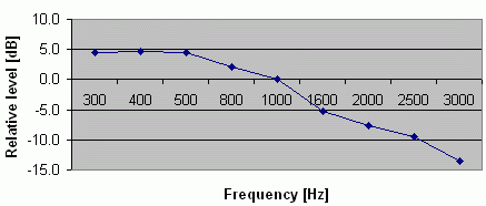
The audio performance was fixed to be nearly flat by modifying a repeater controller capacitor value. Here is the pre-modification audio–very bassy.
This is corrected to 0 dB at 1000 Hz.
The repeater had about +3dB gain at 1000 Hz.
Ideally, the passband would be a flat line at 0 dB—the data shown here is characteristic of a non-pre-emphasized transmission.
Normalized bassy repeater audio--should be flat
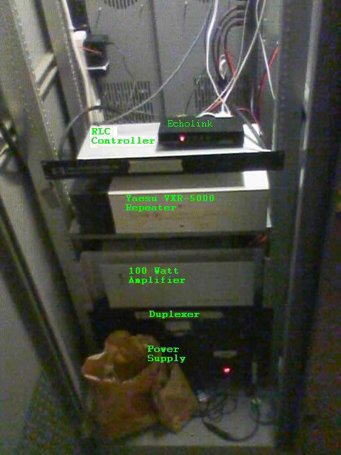
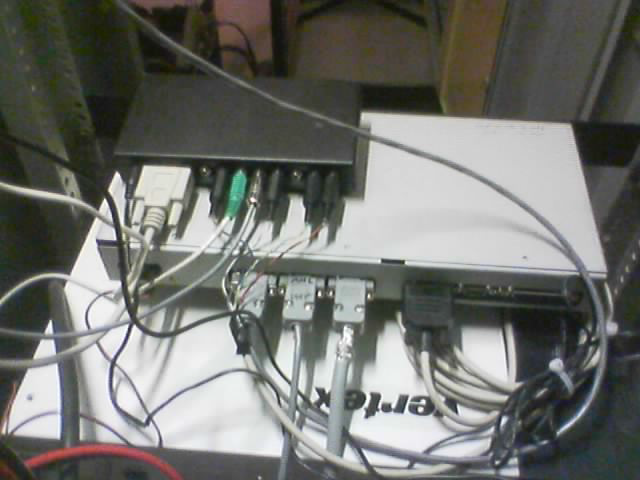
100 Watt UHF repeater system
view of repeater backside
The repeater controller was programmed to switch channels on the repeater, in effect turning the PL transmit on and off at certain times.
One of these “off” times was during the “hang time” of the repeater, which is the period after a system user stops transmitting and before
the repeater stops transmitting.
This hang time is usually several seconds long to avoid excessive wear on the repeater, and to avoid
having to reinitialize PL detection on all the system receiving units for each transmission, which can cause the first word to be missed in a transmission.
The cause of the audio dropouts was narrowed down to the repeater not being able to handle fast, repetitive transitions in channel switching as occurred during weak and fading input RF signals.
Randomly, the transmitter would get stuck NOT transmitting PL during a user’s transmission, causing the repeater to stay transmitting, but the audio to be lost.
The channel changing output was thus disconnected to avoid this issue, and because PL disable is undesirable in radios systems from the 1970s onwards.
Some repeaters are not able to close the squelch quickly enough after non-reverse burst PL users have ceased transmitting.
This causes a “squelch burst” of noise to be heard after each transmission.
On this repeater system, this squelch burst was measured to be 50 to 150 milliseconds long.
This squelch burst can be completely removed with a digital delay module such as the RLC-ADM.
It was discovered that the RLC-ADM digital delay module was in the RLC controller, but was not connected to the COR line.
This caused the RLC-ADM to not function fully due to it “free-running,” not knowing where to start and stop passing audio.
Upon connecting the RLC-ADM to the COR line and increasing the storage time of the RLC-ADM, the RLC-ADM was observed to remove virtually all of the squelch burst, yielding less fatiguing operation for system users.
The audio passband of the repeater was checked using a digitally generated tone source as well as the repeater’s internal tone generator.
It was noted that the input/output ration was not 1:1, rather, a tone going into the repeater would come out at about 75% of original
strength. This caused users to have to talk louder or closer to the microphone than normal.
Also, users seemed to have “pinched” audio as compared to simplex operations—some loss of fidelity is inevitable when
operating through a repeater, but the audio seemed to have a notable dip in low and midrange, and a pronounced rise at high frequencies.
The cause of this was identified as ungrounded audio—the audio ground on the repeater was not connected at all.
This caused the impedance to be indeterminate, and the natural capacitance in the repeater and controller acted like a filter of unknown characteristics.
Once the audio was appropriately grounded to the proper pin on the repeater, and an additional ground was provided for control signaling, the audio
characteristics became more normal—BUT—now they appear to have the characteristics of a non-pre-emphasized repeater input—the repeater must be reconfigured for pre-emphasized audio.
The RLC controller had deemphasis disabled, possibly to help the previously distorted audio, but it must have deemphasis enabled since all end users will have preemphasized audio.
Now that everything else is to normal, the repeater was reconfigured to accept normal audio.
The Voice Prompt level was noted to be at about 4 times the level called
for in the controller manual. The level was reduced by 75%, to about
2kHz as called for in the controller manual. This caused the voice
prompt to be at a natural level and to not splatter adjacent channels.
The Tone level was at about 3 times the level called for in the RLC controller manual, so the level was reduced by about 65% to 1.5kHz as called for in the RLC controller manual.
This caused the tones to be at a more natural level and not disturbingly loud.
Also, because the RLC-ADM was now properly connected, the DTMF cover tones could be disabled since the RLC-ADM mutes the tones.
The cause of the very bassy audio from Internet was due to the ungrounded audio as noted in item 3.
Once the ground was appropriately connected, the audio was normal except for the cause listed in item 3 that must still be resolved.
The whining noise came from a ground loop caused by not having a proper separate control and audio ground—the PA fan noise was being modulated.
Once the repeater grounds were connected as noted in item 3, and the levels were realigned, the whining audio problem was resolved entirely.
The tinny audio to the Internet was because the RLC controller has deemphasis disabled.
Now that deemphasis is enabled as noted in item 3, the audio is normal to the Internet.
The VXR-5000 repeater provides an analog voltage relative to received RF signal strength from about 1 to 6 Volts DC.
This level exceeds the 5 Volt maximum analog input of the RLC controller.
Because this function was not configured, the quickest resolve was simply to disconnect this input until a proper voltage divider would be constructed if this feature is desired at some future date.
Control signals between repeater & controller were ungrounded.
These issues were unexpectedly discovered while tracing the source of previously mentioned audio problems.
The audio and control seemed to be finding their returns through a connection on the Analog input connection for control, analog sensing, and audio functions—obviously an undesirable situation, causing previously noted audio issues.
Two ground connections were added for audio and control, which had previously been ungrounded.
This resolved the audio issues noted previously and allowed the inputs and outputs to be disconnected due to previously noted undesirable characteristics.
The original plan of using a surface mount toroidal splitter was dashed when the one unit obtained was defective.
Rather than deal with another wait to get another, and for the challenge, we decided to construct a Wilkinson power divider.
We first used a set of approximation functions from Bahl’s A Designer’s Guide to Microstrip Line, in Microwaves, May 1977.
They worked fine for the initial microstrip design, but for a confidence check we ran another set of piece-wise approximations obtained from Gupta’s Microstrip Lines and Slotlines.
No practical two-way wireless system has infinite subscriber capacity in finite time.
For commercial and public safety systems from analog LTR, Multinet, and Passport trunking up through APCO-25, DMR, NXDN or iDEN trunking there is channel access latency.
PTT latency, that is, the time it takes from the user pressing the PTT switch to getting the “clear to talk” tones is a key source of frustration on a trunking system.
Trunked PTT latency is not the same as conventional (non-trunked) users are accustomed to.
They must be considered when designing public safety and utility systems and training their end users where safety of life is as stake.
There are parallels to these problems in conventional systems particularly during adverse events.
We give a qualitative overview of the issues in this article.
These issues apply equally to trunked radio systems on any of the common two-way radio bands.
In the United States the most popular bands are VHF (150MHz), UHF (450MHz), 700MHz, 800MHz and 900MHz.
Other countries have other frequency bands popular for two-way radio.
A lot happens in the fraction of a second between when a user “keys up” to talk and the clear to talk being issues.
Consider this in the light of trunked radio technology being nearly four decades old.
Motorola chose to go with a 3600 baud FSK control channel.
The downside is that channel cannot be used for voice at all, but the PTT latency is significantly lower and the contention behavior (two users trying to PTT at same time) is vastly better than for LTR systems.
Motorola Type I and II systems use a single sine wave “connect tone”, which is like a CTCSS code, but one that is used across the system.
Connect tone is analogous to:
SAT tone in AMPS
Color Code in Passport
Area Code in LTR
System Key in Multinet
A brief burst of disconnect tone avoids tail bursts of noise.
The repeater transmits to the subscribers a subaudible 150 baud “OSW” during voice transmissions, subaudible data of increasing complexity with newer Motorola trunked systems.
This is necessary to allow priority override of transmissions (“calling all cars”) and other advanced signaling.
A key advantage of Motorola trunking (and all other trunking except LTR) is that individual subscriber radios can be individually disabled on a repeater.
This helps ensure that all radios used are paying the monthly per-radio rate.
For public safety and other systems, lost radios can be disabled “stunned”.
Clearchannel LTR uses a 300 baud FSK subaudible signaling, so that voice and data flow on any channel in the system.
A consequence of the higher baud rate than DPL or Motorola OSW is that LTR has a more audible background noise, that some users have compared to a diesel truck idling.
Passport likewise has higher “wub wub wub” digital subaudible interference in the audio.
Without custom programming on the radios, the LTR subscribers have to request a channel each time, there is no “memory” of the last used channel without custom repeater controller software.
This means the relatively fragile and lengthy LTR channel request is repeated each and every PTT.
As long as a radio is listening on its home channel, priority override transmissions (from a priority talkgroup) can occur.
If a user has trunked away from the home channel, priority override won’t work until the transmission ends.
Custom repeater software (MultiNet) could drop non-priority calls (cease transmitting) to force users back to home.
Passport systems have optional ESN validation, which occurs upon turn-on
(or as soon as the radio gets in range of a system).
Keying up on a Passport system takes just a bit longer as the MIN is transmitted along
with the desired talkgroup.
From slowest to fastest keying in the discussed systems are: Passport, MultiNet,
LTR-Net,
ESAS, LTR, Motorola Type II/I.
LTR-Net, ESAS and the constriction of two-way radio:
Despite some eye-popping investments including by those turning their Nextel-bought SMR back into trunked radio, I don’t hear about these system anymore.
With the most widespread first generation trunked system (LTR), there was a pent up need with no alternatives.
That is, the wireless two-way dispatch choices through the early 1990s were:
conventional (PL/DPL)
trunked (LTR, Motorola Type II/I, MARC/EDACS)
analog/digital cellular
Conventional and trunked two-way radio were offered at monthly prices of $15-$25/radio depending on system coverage, competition, etc. with effectively unlimited minutes typically.
Cellular by the mid-1990s was settling down to roughly $100/month for light to moderate business users.
Two-way radios had a payback time of easily a year or less through the mid-1990s.
Then the digital cell phone resolution hit, allowing several digital phone conversations to fit in the space of one analog cell phone conversation.
PCS and other spectrum auctions of the mid to late 1990s brought a multiplication of spectrum available for voice and soon more and more data with the mobile internet coming at the millennium turn.
The goal of the cellular carriers was to push ARPU higher and higher naturally, from $60 to $80 a month.
Texting suddenly became something to charge $10/month for.
So one could argue that business cell phone monthly prices had stopped falling drastically by about 1995, and more slowly went up and down depending on what addons corporations wanted.
What brought the constriction of traditional two-way radio shop business models in the early 2000s was a confluence of factors including:
highly-reliable, stable radio circuitry lasting 5 years between repairs, mainly to physical wear
#1 hastened the attrition of an aging workforce, where companies like Bearcom and many others offered flat-rate repair, with their business model allowing whole-board replacements on the backs of other radios fixed cheaply
Psycho-social: as cell phones trickled throughout white-collar to grey-collar, the site managers started “forgetting” to turn their radio on, or “not hearing” calls through an “intermittent” radio. Once those excuses worked for the foreman, the rank-and-file started using them. After a few years, they all had cell phones and $100 worksite simplex walkie talkies.
The high-margin two-way radio business that remains includes
industrial customers that pay someone to handle their problems, that don’t want to assign someone to ship/receive radios to Bearcom. They appreciate quick fixes.
medical customers that need help getting radio systems to work throughout their dense and expanding campuses. No Wifi radios yet.
educational physical plant and security; similar to medical they have big and growing campuses. Cell phones don’t always work in the basements they need to ply.
City/county utilities and services: a long mainstay of radio. Just too many radios to replace with cell phones, their accountants wouldn’t like it given great ROI of self-owned two-way radio systems.
the obvious public safety and critical infrastructure that are mainstays for at least another decade.
You will notice the issue–the five categories of high-margin customers remaining in two-way radio ALL run their OWN radio system.
The long tail of commercial users dried up considerably over the past decade.
Of course, there are still farmers, taxis, construction and other vertical markets.
Looking at each of them in turn:
farmers: highly seasonal use patterns. Local cell companies accommodate with seasonal turn on/off of phones. Low minutes used
taxis: quick blip of Nextel Direct connect gives pickup address. Less than minute call upon passenger pickup. Company margin high, demand growing, coverage area expanding. Not a dead two-way radio market, but shriveling
construction: Cheap jobsite repeaters and cheap two-channel radios are all most need. Even the average joe has a cell phone now, after a few months their foreman gets the number.
and so on.
As service companies (and every other company type) consolidated in the early 2000s, their workers covered larger areas, outside even the reach of a single two-way radio provider’s repeater network in too many cases.
Thus, even the first-generation commercial trunked network systems like LTR-Net (1999) and ESAS (1996) came too late, they effectively came post dot-com.
A key distinction with Trident Microsystems Passport is they came at it from the Motorola angle, going for a higher-end market (actually mid-tier).
Now in 2005, the bulk of the two-way radio business is split from low to high tiers:
conventional repeater users: small construction companies, other small users that are too big to switch to cellular but small enough in number and usage to bother switching to trunked (yet). They are profitable even if the old repeater has to be replaced with a trunking/conventional repeater.
trunked LTR users: coming off of SMR, these are the bread and butter. Still good for $20/month/radio
networked Passport users: for those taking on the risk, can you charge them extra for the infrastructure costs or will they just go cellular
self-owned users: one-time profit + maintenance
The April 2005 announcement of digital NXDN at IWCE may slow big investments in Passport.
Another big manufacturer is said to have commercial digital radio in the works to compete with NXDN.
Physical and Engineering Causes of Trunked Radio System PTT Latency:
Four causes of PTT latency in analog and digital trunked systems are:
Poor SNR (subscriber → tower or tower → subscriber)
System overloading (all channels busy or too many suddenly try to transmit)
Malfunctioning radio/tower radio
Poor RF design or interference (radio or system)
Let us examine these in turn. In Part 2, we will do quantitative
simulations of each failure type.
Wireless communications, particularly of the NLOS variety experienced in typical two-way radio is characterized by deep fading.
The frequency of the fading is influenced by wavelength, hence why 800MHz and 900MHz sound so much more “fluttery” in analog systems vs. 150/450MHz.
Digital radios use signaling designed to statistically fight fluttering, and so effective system coverage quality for a given DAQ can be much larger, tens of percent larger.
Distinct techniques are employed by radios and repeaters to handle the errors in the subaudible data, which has led to lawsuits over
copyright issues.
With the long PTT cycle time of LTR, there is a real chance of two users keying at the same time, effectively jamming each other until one or the other gives up. On systems where too many users are on one home channel, this becomes more problematic and even an ongoing problem.
If a radio is off frequency, or a repeater modulation balance is misaligned, this can lead to significant digital bit error rates, and intermittent performance at any signal level. [to be continued]
In any trunked system, control/home channel performance is precious.
Multinet and Passport work around some of this by breaking up home/control channel functionality into two or three channel all the time.
Nextel interference, co-channel interference, adjacent channel interference can pop up unexpectedly.
We provide assistance in evaluating whole-system performance.
Sometime simple fixes implemented on a first site visit can improve your radio system performance.
Why the gaps right at the most useful frequencies?
Because of
FCC R&O 99-58,
38 dB of rejection for 12 dB SINAD signal in the Cellular Block A and Block B bands.
This was an update to
FCC ET Docket 93-1
establishing the obligation of OEMs to block Cellular Radio Service (824-849, 869-894 MHz) reception after some embarrassing VIP eavesdropping scandals.
OEMs may block image frequencies such as the 902-928 MHz band that would be very useful for amateur radio operators to receive on.
The Yaesu VX-7 has a fourth-order varactor-tuned bandpass filter comprised of HVC355B varactor diodes (D1015 and D1017) with parallel inductor tank circuit for each section of the filter.
The IF frequency is 47.25 MHz, and Yaesu is blocking the first and second image frequencies, hinting that the Q of the filter is low–very broadband.
IF image matrix vis Yaesu’s frequency blocking strategy:
824-2*47.25-0.45=729.05 MHz ← right where Yaesu starts blocking frequencies.
849-2*47.25-0.45=754.05 MHz ← OK, that’s blocked, but they wait until 758 MHz to start allowing reception. Design fluke?
869-2*47.25-0.45=774.05 ← they start blocking again
894-247.25-0.45=779.05, 849-47.25+2 0.45=802.65 ← I guess they rounded up to 803 MHz
869+47.25-2*0.45=915.35 ← rounding down to 915 MHz I guess to start blocking
849+2*47.25+0.45=943.95
869+247.25-2 0.45=962.4 ← rounding down to 960 MHz?
894+2*47.25+0.45=988.95
So that means it’s the first image that’s an issue–isn’t that what the tunable bandpass filter in the first IF is supposed to be for?
Usually we expect 50-70 dB image rejection.
Clearly that’s not the case here, hence the frequency gaps.
12.5 kHz channel compatibility: the VX-7 has filters only for 25 kHz channels.
The transmit deviation can be reduced, but the receiver will still be vulnerable.
Split PL/DPL tone: the VX-7 can only do a mix of PL/DPL split, you can’t do distinct TX/RX analog PL tones.
Some repeaters with high altitude and/or voting receivers use DPL on the repeater receiver input, and transmit with analog PL.
This is sensible because repeaters are targeted toward mobiles and portables, and maybe base stations with directional antennas and low power.
Both in the commercial and amateur world, base stations with high power omnidirectional transmissions clog up distant repeaters, particularly at VHF where tropospheric ducting is more common.
Why not use DPL for both transmit and receive?
Because DPL has worse decode sensitivity than analog PL, particularly for low-quality decoders.
The repeater will have a high-quality DPL decoder, and the mobile is unlikely to hear the distant repeater, so analog PL receive is good for the mobiles, why give a double SNR decode penalty with DPL TX/RX.
For a system targeting wide geographic coverage, two alternating repeater RF output frequencies might be used, and keep the same PL for simplicity.
The systems can be linked via RF or VoIP backhaul, and the end user selects which repeater receives them by switch mobile transmit PL.
If the systems are unlinked, interference is avoided since everyone hears the overlapping repeaters.
This is something the VX-7 cannot do, without using PL on transmit and CSQ receive.
Modern cars and environments have a lot of RF noise from computers and communications.
Carrier squelch will breakthrough not infrequently on nuisance interference.
Repeater should transmit coded squelch so users can filter out background RF noise.
The RX sensitivity specifications are easily met.
We hear airplanes a couple hundred km away on VHF AM airband (108-136 MHz).
Sirius XM receivers began wide availability factory-installed in automobiles in the early 2000s.
Both Sirius and XM use left-hand circular polarization (LHCP).
The authorizations allow future flexibility to use RHCP to get polarization diversity multiplexing, which could someday increase throughput within the limits of cross-polarization performance of end user antennas.
XM Radio reception is possible inside a metal structure (walls and ceiling) where we were unlikely to be within range of a terrestrial repeater.
The key factor to XM Radio reception indoors from the vehicle was that the metal garage door nearest the vehicle were open and south-facing.
Lets examing the SDARS link budget.
SDARS XM/Sirius Radio link budget:
While XM uses a significantly more sophisticated modulation and interleaving scheme than Sirius, for simplicity let’s use Sirius’ simpler 4.5 MHz QPSK single stream as the model since it will perform worse than XM in general.
That is, a single QPSK stream at 4.5 MHz RF bandwidth will get a Sirius radio to play music.
EIRP satellite ~ 90 dBm (1 MW)
Thermal Noise power in 4.5 MHz BW: -107.4 dBm
Elevation angle: 30 degrees (roughly based on latitude ~ 49 degrees ~ worst azimuth)
Path loss to geosync at 2.345 GHz ~ 192 dB
Rain loss ~ negligible
Sirius/XM Radio link margin [dB] = 90 - 192 -(-107.4) ~ 5.4 dB
This is within reason for 10^(-4) BER with QPSK and Reed-Solomon.
While I would assume the highly simplified calculation above neglects a few dB (is too conservative) this shows it’s within the realm of reason, and that a big unfurling antenna on the satellite is important for more gain.
Spatiotemporal diversity is a very important factor, yielding ~ 10 dB of effective gain under many scenarios.
Foliage drains back another few dB statistically.
Basically, it’s give and take, and it seems likely a great amount of effort was spent modeling and measuring.
XM Radio FCC Authorization cost $90 million in its winning bid, FCC DA 97-2210 authorization order coming in October 1997.
The frequencies from 2332.5-2345 MHz were authorized for XM Radio broadcast of various services including voice and music subscriptions.
Late in 2001, XM Radio finally became publicly available using two geostationary satellites: “Roll” at 85 West and “Rock” at 115 West using LHCP S-band antennas.
The terrestrial repeaters use vertical polarization, which is received with 3 dB loss by the LHCP end user antennas as implicit in linear vs. circularly polarization antennas in the same system.
XM Radio Technical characteristics:
March 2001
FCC Order DA 01-699
increased XM Radio EIRP from 62 dBW to 68.5 dBW (that is, from 1.6 MW to 7.1 MW).
The frequency authorization consists of four 1.84 MHz space-to-earth channels and two terrestrial repeater channels each of 2.53 MHz.
The center frequencies are:
Roll: 2333.465 MHz, 2344.045 MHz
Rock: 2335.305 MHz, 2342.205 MHz
Terrestrial: 2337.490 MHz, 2340.020 MHz
XM Satellites are bent-pipe transponders from X-band to S-band, like Sirius.
FCC Order DA 01-2172
on Sept. 17, 2001 gave an STA (Special Temporary Authority) for the long-anticipated terrestrial SDARS repeaters, ultimately necessary even for the elliptical Sirius orbit and much more so for the geostationary XM orbit (parked over the equator).
This STA gave the OK for 180 days of 2 kW EIRP repeaters in general and specifically listed > 2 kW EIRP repeaters.
The repeaters had to be the whole channel set completely matching the satellite broadcast–working to stave off fears of custom local terrestrial channels only on the repeaters for a particular city.
May 18, 1990 was in a way the initial firm public step towards US mobile satellite radio with Sirius FCC application.
October 1997 Sirius was initially authorized in
FCC Order DA 97-2191
for the 2320-2332.5 MHz band using LHCP (left hand circular polarization), for which it paid $83M the same calendar year.
7025-7075 MHz was authorized for co-primary uplink for SDARS.
Service was planned to launch in late 1999 for the “lower 48” USA.
Initially Sirius planned to have two geostationary satellites – before launch, altered to be elliptical “tundra” orbits.
The Sirius service was initially planned to have:
thirty 128 kbps channels “CD quality”
twenty 32 kbps channels “FM quality” for voice programming
option to divide these channels as much as needed for auxiliary non-voice service
Of course what happened was that these channels were sliced even more finely to get the ~100 channels.
The digital compression artifact are readily apparent on Sirius as well as XM.
However, to most users they prefer dropouts vs. changing the radio station frequently or the pops and fizz of VHF WBFM multipath and fading combined with the high SNR requirement for FM stereo, and receivers that wait till SNR is too low to revert to monaural reception.
Terrestrial repeater authorization was explicitly deferred for a future authorization.
Early in 2002, Sirius finally became publicly available after years of wrangling with diverse and even humorous opposition reaching FCC filings over 12 years.
Distinctive from XM Radio receivers’ six simultaneous RF broadcast streams (two from each satellite, and two terrestrial), Sirius receivers use three streams (one from each of two active satellites) and one terrestrial.
Sirius receivers (end user) have three channel simultaneous receivers for time and spatial diversity (simultaneous tuning of two satellites and one terrestrial repeater).
Sirius rotates which two satellites are active as the three (FM1,FM2,FM3) Sirius satellites pass over North America for best coverage of CONUS.
Each of the two Sirius satellite channels are 4.5 MHz using QPSK modulation.
Each channel is a copy of the other, with a 4 second time delay for time diversity (e.g. overpass, tree cluster).
The net Sirius satellite data throughout is 4.4 Mbps all-inclusive – voice, music, data, telemetry.
Each Sirius satellite is a bent-pipe transponder from X-band to S-band, and the downlink channel is selectable in case of needing to swap out for a bad satellite.
The single Sirius terrestrial repeater channel is also 4.5 MHz, but uses a different modulation scheme.
July 2000
joint FCC-State Dept announced
that agreement had been reached with Mexico for SDARS frequency bands, including terrestrial repeaters that had already been agreed to by Canada and the USA.
The specific terrestrial SDARS repeater frequencies were:
XM Radio: 2336.225-2341.285 MHz
Sirius: 2324.3-2328.3 MHz
Reference: Elbert, Bruce R. The Satellite Communication Applications Handbook. Artech House Space Applications Series. 2nd Ed. (2003).
For sound card amateur radio modes a simple SoundBlaster USB soundcard as the ADC & DAC on the built-in sound card didn’t have adequate SNR.
With the Icom IC-725, PSK31 works quite well on the USB sound card–since I don’t want to splash 3 kHz at 10 mW of internal soundcard hash on the air.
On CB 27 MHz it’s hard to talk to base stations 25 km away during the day–a striking difference from a few years ago when the sun was quiet.
But this means a boon of DX on ham frequencies.
Radio Coverage Map verification and range test of such radios is as follows: put the base station into VOX mode, and setup the PC to play a tone N seconds long every M seconds.
Then, setup the PC to simultaneously record continuously (or use a separate recorder).
Now you have a timed radio coverage system–synchronize your watch and PC clock.
Then, even for the maximum range case where your base will hear the mobile but not be able to understand it, because you record your location vs. time in the car, based on the number of beeps you can match unreadable transmissions with where you were–which is often more important than where you can hear!