Public safety is ensconced below 860 MHz while Nextel blasts away with wideband CDMA above 862 MHz.
A police station was missing every fifth or so radio transmission.
This immediately raised some ideas, since the trunking system was 5 channel, of the type that used a low-speed subaudible data control channel shared with voice.
While transmissions that worked were heard crystal clear, due to the quieting effect of FM, we know that there is a rather non-linear relationship between C/N and SNR.
That is, the FM improvement factor once you’re over the signal level where popping and cracking stops puts you quickly to the 35dB maximum SNR typical of FM communication radios.
The link could be weak but you’ll only intermittently see problems.
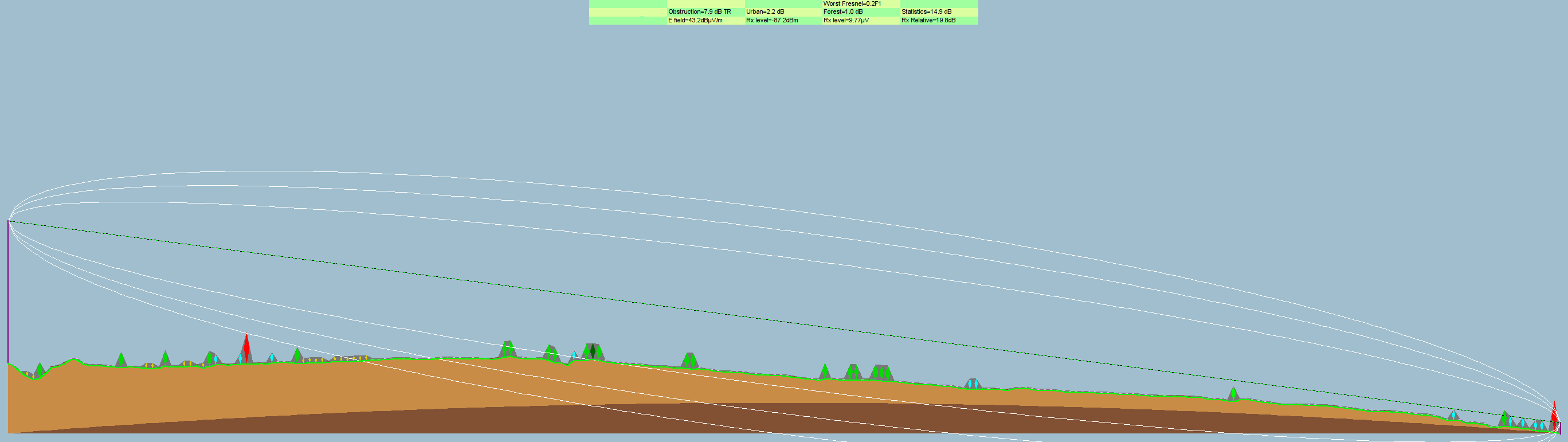
We used
Radio Mobile Deluxe
for a “radio link” path simulation as seen at the top of this article.
The over 40 km path length despite the mild terrain leads to only 0.2 Fresnel zone clearance instead of the desired ≥ 0.6.
Since this system had only one central transmitter for the county, and the police station antenna was on a tower with a good gain omni antenna, there wasn’t much to do.
The omni antenna had to stay to allow for backup simplex (radio to radio) communications in case the main tower went down–they weren’t going to buy a second base radio or swap yagi to omni antennas in that
case.
Radio Path profile
The deficient design of the county-wide 800MHz system caused a variety of problems due to having the single central transmitter on a tall hill and a very tall tower.
You just can’t be 40 km from a transmitter and get a solid signal when safety of life transmissions are concerned.
Yes, ham radio operators go over twice that distance on VHF/UHF repeaters, but two key distinctions are:
Ham repeater frequencies are generally afforded far more co-channel and adjacent channel protection than commercial frequencies
Ham radio operators will tolerate far more static, fading, repeating transmissions than police officers in hot pursuit
In fact, given terrain in other parts of the county, some places only 20 km from the tower had problems with reception.
Yes, there was a receiver voting system, but in a trunking system, you have to hear the base station before you can initiate voice communications!
You can’t say “man down” on a trunked system even next to the voting receiver if you can’t hear the base transmitter.
Exception is for the emergency button, the protocol designers were smart enough to allow the emergency unit ID to go through even one-way.
We set a conventional receiver to each of the channels and listened for the 10-second periodic “kerchunk” of each repeater.
We noticed the repeaters were roughly the same signal strength by ear.
No other complaints had come in besides the usual.
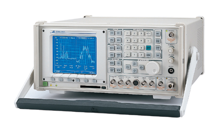
We did a few test transmissions at the police station from their radio, tested their radio with an Aeroflex COM-120C service monitor, checked the SWR with a Bird 43 wattmeter, all was well.
Aeroflex COM-120C service monitor. Photo copyright Test Equipment Connection
The spectrum analyzer showed the 5 repeater channels were approximately equal in strength, allowing for fading and instrument accuracy.
The received signal amplitude was in line with the path loss predictions, keeping in mind the confidence interval in the Longley-Rice propagation model.
We reprogrammed the police base station to listen directly to each of the channels.
We noticed a clear SNR deficiency on only one channel, despite the spectrum analyzer showing nearly equal signal strengths and equal background noise level within the sensitivity of the spectrum analyzer.
The spectrum analyzer intrinsic noise floor was on the order of -100dBm for the resolution bandwidth.
Spectrum analyzer resolution bandwidth trades resolution for update rate.
Large resolution bandwidth gives very rounded-off traces at decent update times.
Small resolution bandwidth gives fine traces at slow update times.
Nextel’s iDEN signals fill the channel with a fairly uniform spectrum.
You can’t zero in on a carrier like you can with analog transmissions and wait for the analyzer to update.
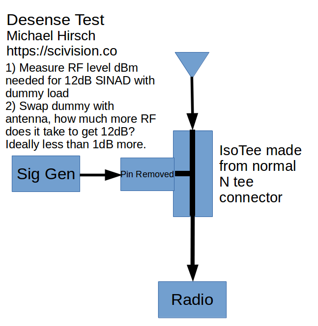
The “desense” test uses a special T-connector called an isotee that passed straight through between antenna and radio, and the T port had the center pin removed.
The isotee provides controlled (at least at each frequency) isolation such that a signal generator connects to the isolated port, and the radio is connected to the antenna via the other two ports.
isotee diagram for desense check
Four channels were normal, perhaps less than a dB desense.
The fifth channel had perhaps 10-20 dB of degradation, fluttery time-varying.
Changing the signal generator frequency slightly did not generate beat notes.
Tuning the radio/sig gen to one 25kHz channel either side didn’t have the interference.
The interference was fluttery but constant otherwise, no duty cycle.
Nextel despite purchasing up SMR licenses in those days did not put sites at the license coordinates necessarily.
They took advantage of the SMR regulation allowing different site location as long as the license footprint was not exceeded.
This is where the cell phone DXing came in.
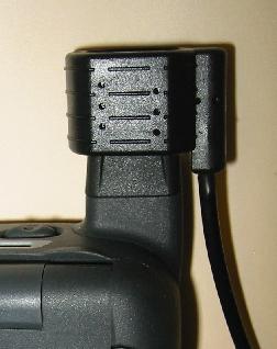
We used a Wilson antenna adapter on a Nextel i850.
Dialing # , * , Menu, Right to go into field test mode, gave current frequency and signal strength in dBm, among other parameters.
Wilson Antenna coupler slid over Motorola i850 antenna, allowing use of external antenna for far greater range (photo copyright Wilson Antenna)
There was not cell service locally available at ground level.
With an external antenna the Nextel signal was there.
he Nextel phone showing similar signal strength on the Nextel signal as what the non-directly observable interference might be.
Nextel field engineering staff were a bit surprised that a Nextel tower over 90 km away could be a bother to a police radio.
We noted the weak desired signal, and the part of the interference path that went over water.
This configuration was conducive to thermal inversion layers.
Superrefraction can make radio waves travel unexpectedly long distances.
He put in a channel change request.
The desense test then showed all repeater channels were good.
Hopefully someone at Nextel did a license search to give a wider co-channel geographic exclusion zone for public safety licensees.
It would be a simple FCC license search away.
SCADA systems from Mitsubishi Alpha to MOSCAD can use wireless networks such as MDS microwave relays.
Critical infrastructure systems own radio networks help maintain control in the face of a major telecom failure.
Leased lines are too expensive, POTS dialup can be fidgety.
Municipalities and utilities small to large can’t afford to rely on weak communications command and control linkages.
Old systems based on DTMF or proprietary signaling systems can be replaced with MOSCAD or the like having timestamped, encrypted anti-playback capability.
No factory-default passwords, make the SCADA equipment require a sufficiently sophisticated password.
Find ways to make certificates and other “beyond password” measures a reality with embedded critical control systems.
Sometimes adding just 2% percent to a system cost adds 15% more value.
For example, using narrowband data to pumps and broadband data to substations can reduce antenna needs for the narrowband stations, allowing increased robustness in remote areas.
Triggered camera recording with periodic snapshotting allows identification of malfeasants over a modest data pipeline vs. thousands of hours of unwatched video.
Instead have high speed video when the installation is approached.
These approaches exploit the latest in encrypted, license-free data radio technology, allowing rapid upgrades without dealing with contentious cross-border licensing issues.
The higher directivity of 900MHz yagis vs. VHF yagis allows denser networks and less interference from tropospheric ducting a.k.a. “skip” from hundreds of miles away.
Multipoint operation reduces the need for a tall central tower(s)–or have multiple supernode locations with more modest elevation.
A particular entity used two-tone paging for life-critical voice paging across a county-wide area.
They wanted a backup paging system that could work in a standalone fashion without any other infrastructure.
In case of a major system/telecom failure, they could still send coded one-way broadcasts to key agencies.
They had been sold a system using a mobile two-way radio in a suitcase with antenna, which transmitted to other two-way radios tied into each paging base station to control the powerful paging transmitter.
After a cursory examination I could immediately see why this system worked poorly under real life conditions.
Part 1 of this case study details qualitatively what was wrong, and Part 2 will look at simulation in GNU Radio.
good remote two-tone paging link design
Old, undesired remote 2-tone paging
Every connection on the diagram except the antennas is wrong.
I gathered up all the items except the paging transmitter back to the office.
Let’s go from right to left in the diagram above, exploring what needs improvement.
They needed to use speaker audio to get enough amplitude to go into the 600 ohm line input of the transmitter.
They used a resistive voltage divider where an 8 Ω resistor was connected across the speaker output, and each side of that 8 ohm resistor went through something like a 1000 Ohm resistor to each side of the line transformer.
This was not impedance matched and so the frequency response of the main line connection as well as the paging backup was distorted.
The volume control affected the paging levels from the backup.
The carrier squelch receiving CM200 would hear all signals on the UHF frequency.
The only thing stopping anyone from blasting out messages across the whole county was the fact that no one else sent tone remote controls across the air.
The non-flat audio meant with the 2175 Hz and 1950 Hz control tone levels OK, the low frequency two-tone paging would be too low.
Don’t send sensitive control tones across the air, the dynamic range of a radio channel isn’t wide enough and the interference rejection (capture ratio) isn’t high enough with the insufficient dynamic range
Don’t do critical functions across a carrier squelch link!
Don’t use non-flat audio for links, it’s hard enough to get the levels right with flat audio
The transmit CM200 at least complimented the settings of the receive CM200: carrier squelch, preemphasized audio.
We would reprogram this radio to suit a more stable, secure system in the next section of this case study.
The Zetron tone remote was hacked to add a PTT relay and cutting down the audio level to feed a microphone input on the CM200.
This should have been left factory, and use a tone remote interface on the transmitting CM200.
The engineering issues starting with the most severe included the following.
Sending level sensitive tones over a link with insufficient SNR.
The SNR of a narrowband commercial radio is about 35-40 dB.
The dynamic range of the control tones is 30dB, as follows.
+10 dBm 2175 Hz
0 dBm 1950 Hz
-20 dBm 2175 Hz for the duration of the transmission.
A POTS line has SNR in the 35 dB range for a good signal, limited by the ADC/DAC PCM conversion and hardware.
Apparent SNR seemingly higher than 35-37 dB is observed by compressing the audio, but a careful test will show the actual instantaneous SNR when PCM is involved as in any modern POTS line won’t be higher.
So why didn’t the radio link with 35dB max SNR work when the POTS line at 35dB max SNR works all over 24/7/365?
The POTS line does not experience nearly the same impairments that a typical radio channel does.
The tone remotes are designed to withstand oddities of POTS behavior, NOT radio link behavior.
Consider the deviation level if we put the +10dBm 2175 Hz tone to have 70% modulation, that is, ± 1.75 kHz deviation in a 12.5 kHz bandwidth (± 2.5 kHz max deviation) system (the current FCC standard for commercial two-way analog FM).
We don’t want to go any higher than that because the deviation limiter of the radio starts to kick in, making the tones non-linear.
Then the other tones will have deviation as in the following table.
Tone level (dBm @ 600 Ω)
Deviation (± kHz)
Tone freq (Hz)
+10
1.75
2175
0
0.55
1950
-20
0.032
2175
The last row of should set alarm bells off.
32 Hz of deviation is an extremely low level, a level of perturbation that easily comes about from noise and interference.
Beat notes from another FM transmitter on the same channel can create energy in bins near the 2175Hz guard tone that false the decoder and cause the paging system to stop transmitting.
Part 2 will show a simulation of this effect; it’s immediately apparent.
On modern POTS lines crosstalk and beat frequencies aren’t such an issue anymore.
The tone remote systems weren’t designed to tolerate this.
Using a carrier squelch system for a critical system backbone function is very inappropriate.
Use some type of signaling qualification at least as secure as other elements of the system, even if it is security through obscurity.
Sending non-flat audio over backhaul is troublesome with level-sensitive signaling.
It makes low frequency paging tones have low SNR, which is then repeated out the paging transmitter as a degraded signal, causing poor coverage for jurisdictions using low audio frequency two-tone pages.
Preemph/deemph is to help fading radio channels have less of a hissing sound, it’s not beneficial for what should be relatively strong signal links.
It doesn’t help co-channel interference.
The impedance matching problem was not helping frequency response of two-tone paging either.
For each problem noted in the last section:
Use standard radio signaling techniques (simultaneous subaudible modulation, tone burst at start of transmission) to act as the authentication.
This was no worse than what the rest of the system used.
The risk of intercept was small, and if an adversary had the equipment to get the radio codes, they could have simply gotten the radio codes for the rest of the system with less effort.
This meant that there would no longer be tone remote 2175, 1950, 1850 Hz signaling going on over the air, and the two-tone paging would be set for 66% modulation (+/- 1.65 kHz deviation) allowing maximizing SNDR (noise + distortion).
This was enabled by using a Vega DSP-223 tone remote panel between the Zetron and the CM200 radio.
This solution ties in with number one, +/- 300Hz deviation subaudible digital signaling was used continuously during the transmission, along with a brief ANI burst of +/- 1.5kHz. An ANI validation module managed this qualification on the receiving end. The system will work without ANI, it will just be less secure against others keying up the system.
It was easy to reconfigure the system to use flat audio, it’s just a programming selection and use of appropriate 16-pin connector pins.
Since the paging transmitter had a second local PTT & audio connection, we didn’t connect to the 600 ohm line used by the main consoles. We used an audio transformer to isolate the radio from the paging transmitter, and the signaling decoder provided a relay output to key the paging transmitter. The two-tones were sent from the Zetron after a delay long enough to allow for link receiver decoding (subaudible + ANI + paging transmitter keyup).
Part 2 will explore the quantitative radio link vs. POTS.
A VHF (150 MHz range) police/fire radio system was suddenly suffering from intermittently poor signal from a part of their coverage area, being noticably worse with rainy weather.
On VHF, receiver voter systems are more common due to the much poorer portable (handheld) radio performance versus UHF and 800/900 MHz systems.
We first checked the voter sites nearest the complaints including the line levels at the main repeater/voter.
If voter levels are incorrect, the voter can see this receiver as having poor SNR and always pick other receivers.
The remote voter receiver levels at the central voter were acceptable.
There was no apparent problem intrinsic to the voter site that seemed the likely culprit using the spectrum analyzer, or just listening with carrier squelch.
There was over
5 dB of desense,
but that is not at all uncommon for an urban VHF receiver.
Radio checks with a one-watt portable from the complaint locations, placing a dictation recorder near a receiver tuned to the repeater output.
The dispatcher and recorder heard full-quieting audio, even as I moved around.
But this was on a non-raining day, so we decided to wait for the next rainstorm.
And, we told dispatch to call us on any time they noticed this issue.
On a light rain day, the problem recurred.
I still did not hear anything discernible in the repeater receiver, nor see anything with the spectrum analyzer on the receiver antenna.
The desense test now noted a time-varying 10-20 dB of desense.
That’s enough for the user to notice certainly.
I noticed something interesting about the time-varying desense pattern.
It was not wildly varying, but rather it would spend several seconds at one level, then several seconds at another level.
This was consistent with the VSB analog TV signal behavior.
Cable TV radio interference characteristics: analog VSB TV is amplitude modulated signal with a powerful carrier and a few MHz of bandwidth above the carrier including chroma, luma, sound, etc.
Cable TV signals are just like over the air TV signals, except frequency shifted.
But how would I track this signal down?
The powerful VSB carrier has order(s) of magnitude more power than a narrowband slice of its modulation.
Cable TV channels 19 and 20 are prime suspects, using a cable TV frequency
chart.
For radio frequency is in the 151-157 MHz range tune diagnostic radio to 151.25 MHz, which is the video carrier.
A portable set to this frequency did not hear the signal at ground level at the site.
The cable TV source may be 20-30 feet above ground while the police repeater receiver is 200+ feet above ground.
Tracking cable TV leakage interfering with VHF radio: a VHF yagi would have a distorted radiation pattern from a vehicle anyway.
We used a mag-mount 1/4 wavelength vertical ~ 18" and decided based on the signal strength the leakage was within about 2 miles.
Using binoculars I could clearly see CATV line with what appeared to be fresh work near the interference site.
The cable company came with unprecedented speed, with a pair of senior technicians.
Within two hours of their work the issue was solved.
Seems an old line(s) had been cut and left there, and they weren’t properly terminated.
I suppose the metal shavings and moisture caused some resistive coupling to something else, giving a sharp rise in leakage.
The Sears Tower Skydeck with an FRS walkie talkie and ham radio walkie talkie can yield 50 km line of sight.
With standard 4/3 refraction, and especially under conditions where one can see a mirage of Sears Tower, the RF connection across the lake is possible.
Using Radio Mobile Deluxe, I predict on 2 meters (144 MHz) a signal strength of -87 dBm with 70% spot reliability.
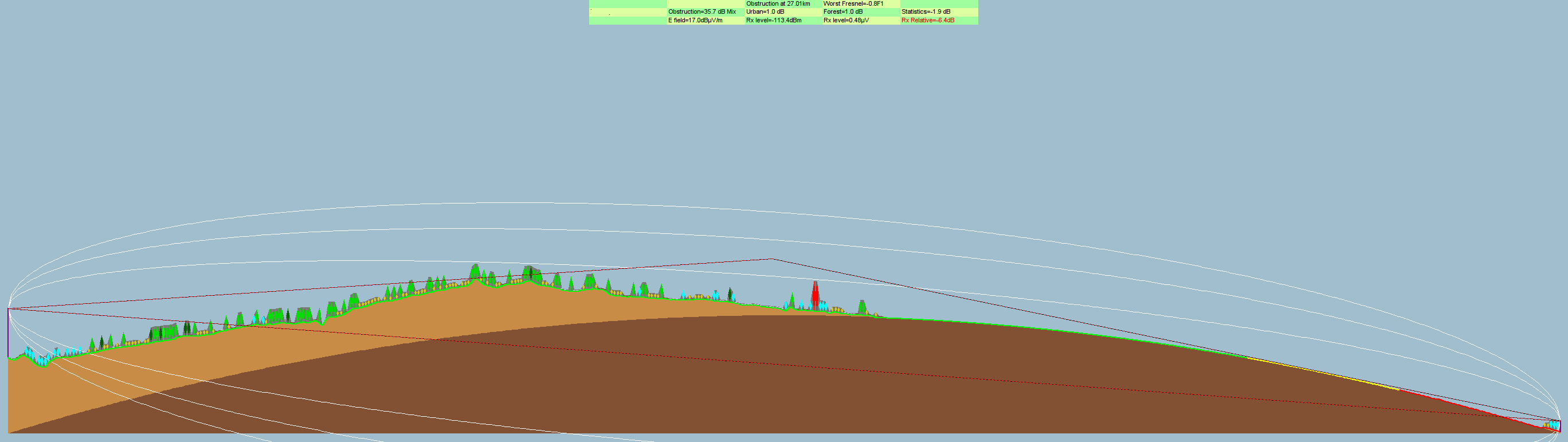
70 cm (440 MHz) is predicted to be -94 dBm.
In pure free space (outer space) we expect a tripling of frequency to increase path loss by
20*log10(3) = 9.5 [dB]
Yet here we see only a 7 dB penalty for tripling frequency.
This is because the Longley-Rice model inside Radio Mobile Deluxe takes into account that (for this path) at 144 MHz the Fresnel zone clearance is only 0.2 and at 440 MHz the Fresnel zone clearance is 0.3.
Fresnel zone clearance relates to Huygens’ principle: at each point in space, we may imagine secondary reradiators.
Thus for a wave front encountering an obstacle, we can model the “bending” around an object into a “shadow”.
This is how we have radio coverage in urban areas, and why mobile radio high gain antennas are worse than
low gain antennas in urban areas.
The Motorola Museum includes an old Centracom console (complete with OOPS code), and old handsets and dual TX-RX units from WWII era or thereabouts.
We saw an RF development lab where they test radios in real world conditions.
They had a spectrum analyzer hooked to a broadband (discone?) antenna.
In the 100-1000 MHz range, the quietest spectral locations were the amateur radio bands, they looked as if there’d been notch filters inserted in line.
Of course that wasn’t the case, it was the relative daytime quiet of the VHF/UHF ham bands compared to the commercial and government radio traffic.
Yes, military aviation UHF was also a bit quiet.
We also saw a CAD lab where the engineers had quad monitors.
With perhaps $1200 in two dual-monitor video cards and $1000 per monitor, and probably a $2000 desktop PC otherwise, that’s about $8400 per workstation in computing hardware.
The productivity gains are compensating for that initial expense.
We also saw the dispatch center where Motorola handles field support calls from contracted end users and support staff.
This might include Motient, large cities and government agencies.
There is a backup center with undisclosed location and different employees as it would be vital in the case of a big crisis.
The wall of the two story room was a giant screen, like one sees for NASA Mission Control, viewable from any of the perhaps three dozen workstations facing it.
I wanted 24 hour (or “military”) time from a bedside alarm clock radio.
The LM8560 datasheet showed that by applying Vss to pin 28, I might achieve 24 hour time display.
First, you must ensure pin 28 of the LM8650 is NOT connected to anything else! Or you might destroy your clock radio when connecting pin 28 to Vss.
In some cases, you may find there is a spot already for a jumper wire to Vss that’s just not been put in at the factory.
After adding the wire, you’ll see that time now goes in 24 hour style…for the “2” in the tens position of hours, it will just light the top segment of what would be a numeral one instead of displaying a “2”, for those displays with only a “1” in the tens hour place.
Clear frequencies are vital for 47 CFR 15.219 unlicensed AM MW broadcasts in the 510-1705 kHz range with 100 mW input power and 3 meter antenna (inclusive of ground lead).
To maximize range one has to consider more than ground conductivity and wavelength.
For licensed broadcasters, there is a presumption (even on the heavily populated local “graveyard” channels) that there is some standoff distance to the next transmitter.
Of course, the reason local AM MW channels are useless (low SNR) beyond 10-15 miles from the transmitter at night is the extremely high congestion (too many close transmitter) on these channels.
The long range of clear channel transmitters comes largely due to the implicitly very sparsely populated channels they exist on.
Of course, that assumes all transmitters have reasonably efficient antennas and ground systems to meet the minimum efficiency requirements of 47 CFR 73.182 and 73.189.
Complex $100 transmitters can have design limitations that are constricting due to the 100 mW INPUT power regulation.
The VEC-1290K is cheap and simple enough to allow for example replacing the inductors with higher efficiency (lower loss) coils.
Add bypass caps to the power supply and check the trapezoidal (X-Y) waveform for proper modulation depth.
Turn the LM386 modulator into a low-pass filter by changing the capacitor, or add another stage with dual opamp and dead-bug wiring.
Selecting AM Part 15 license free broadcast frequency: recent encroachment by second adjacents means at night calls for audio transmit bandwidth 10-15 kHz.
Non-CQUAM car radios might have only 3 kHz of bandwidth.
Center frequency is 1640 kHz has modulation from 1620-1660 kHz at day, and about 1630-1650 kHz at night.
To get the best frequency look two channels (20 kHz) up and down from the intended frequency.
If a third adjacent is nearly (30 kHz) go an extra channel away from them for poor selectivity receivers.
At night it’s tricky to find a full bandwidth clear channel, even in the expanded band, which is the only place for license free AM that gets decent range day and night.
Some commercial stations have full 20 kHz at day but switch to a lower bandwidth 10 kHz broadcast at night on a different channel, maybe one channel up or down.
Note! Unless running less than 3-4 kHz audio bandwidth don’t use 1700 kHz center frequency since the cutoff for Part 15.219 operations is 1705 kHz–that’s absolute, not center frequency of 1705 kHz.
Another trick is for the receiver to deliberately tune off frequency, such that the carrier and one sideband are captured.
This only works for analog receivers of course, and the trend is to digital frequency receivers.
The transmitter can’t slide too far off center for the digital car radios.
Improving Part 15 AM broadcast SNR and range: at nighttime, audio compression would help make apparent SNR higher by increasing the loudness of quiet passages.
Adding an expander circuit to the receivers akin to Dolby B noise reduction would add nearly 10 dB apparent SNR.
Keep modulation clean and near 100% peak to maximize coverage.
High quality audio sources: the fidelity of even 14.4 kbps RealAudio well exceeds that of conventional AM.
Hear distant AM radio stations on an AM radio–via AM transmitter connected to computer internet streaming audio.
The usual phonograph and CD sources (remember licensing for public performance issues) work as well.
Where SNR is adequate and with receivers modified to pass 20 kHz, a Part 15 AM MW broadcast system can exceed the fidelity of FM radio.
The 11 year solar cycle has brought a day of reckoning for CB radio.
The short winter days will give some respite, but skip is sometimes heard when the sun is below the horizon.
A sure sign of increased ionization supporting increased MUF up into the 27 MHz CB radio range.
Shortwave listening in the 5-10 MHz range impacts are not as dramatic for high power shortwave stations vis-à-vis SNR.
With broad frequency choices, ham radio takes advantage of a clearer diversity of frequencies.
If more people used SSB on CB, frequency sharing would be much more efficient.
Without the capture effect of FM, the typical AM mode leads to loud squealing heterodynes.
Narrowband FM on 27 MHz CB radio capture effect wouldn’t be nearly as effective.
GMRS doesn’t have quite the appeal of 27 MHz CB since the user base on 462 MHz is split between incumbent businesses who are in no mood to chat (and may even be paying for a repeater), inexpensive FRS walkie talkies, and lack of enthusiasts.
eBay sells radios from a distant city trading up from crystal controlled radios.
Even the crystal radios are often two or four channel.
We could setup a common calling frequency for chit-chat and then have a second channel for each group.
WLS 890 AM out of Chicago has joined the growing legion of stations broadcasting on the Web.
Using RealAudio format, a good dialup connection can just manage reasonable quality audio.
Usually much better audio than trying to listen with a regular radio despite their immense multi-state groundwave coverage.
The increasing electronics and metal building construction rob indoor listeners of traditional AM radio coverage, and even broadcast VHF FM radio.
This online listening format will probably only grow as internet connections and computers become faster.
Nextel makes deals with SMR operators with fully built and utilized repeater systems.
Licenses were pulled from SMRs that aren’t actually fully built and on-air.
To make a multi-channel trunked repeater from salvage parts, consider filtering and connections.
Unlike lower frequency bands where repeaters like Motorola GR300 or the Motorola R1225 repeater that are essentially refitted mobile radios for transmit and receive, 800 MHz subscriber receiver are not trivally retunable by software alone to the 806-821 MHz mobile transmit band.
The easier plan is take the 1980s scanners being dumped on eBay as people pickup TrunkTracker scanners.
For example, the PRO-2004 has specified 0.5 μV sensitivity.
Since we need a receiver distribution amplifier anyway, just leave 6 dB less padding than before–problem solved!
For filtering, that will be part of the distribution amplifier–it will filter out the strong transmit signal on the separate antenna as well as any lower frequency signals (FM/TV/UHF/VHF) and any higher frequencies (AMPS 850 MHz).
Given the location there shouldn’t be too many strong in-band signals, though overloading is possible within a km or so of the site.
If that became an issue I could put a cavity filter on that channel, again from eBay.
But for simplicity let’s stick with the receiver distribution amp 806-821 MHz filter.
The audio connection is made at the discriminator tap since DC-coupled baseband is needed to retrieve LTR data.
The volume control is all the way down to avoid bothering other workers in the radio room.
Leave the scanner speaker connected for basic diagnostics.
We use the EF Johnson 8600-series radio–get the full feature model with up/down arrows, not the single button model as you need talkaround!
Set the radios to 10 Watts transmit power so that they can handle the duty cycle, and to help reduce thermal cycling stresses.
Program each radio to a single channel, talkaround on the repeater output frequency.
Bypass the microphone jack to get the full non-pre-emphasized DC response to the modulator.
Combiner: any 800 MHz SMR combiner is fine.
Receiver distribution amplifier has three parts: 806-821 MHz combline bandpass filter, amplifier, and splitter.
These tend to come in multiples of four as it’s easier to cascade that way as per Chip of Angle Linear.
I managed to find a used one but in the future I would consider Angle Linear for even higher performance with his 0.7 dB NF amplifiers.
LTR controllers are not particular to the transmitters, but can be particular to each other.
EF Johnson and Uniden use distinct backplane signaling.
Others are switchable via jumper.
Uniden doesn’t need a terminator while EF Johnson does need a 50 ohm terminator.