Image histogram with Imagemagick
Imagemagick can show a histogram from the command line. Do this with Python for programmatic use.
magick input.jpg histogram:miff:- | magick display miff:-input.jpg- image in ANY format to display the histogram
Imagemagick can show a histogram from the command line. Do this with Python for programmatic use.
magick input.jpg histogram:miff:- | magick display miff:-input.jpgEnable Active Mode for an FTP server if unable to list directories in Filezilla or other FTP software.
Make a square-base 2D data pyramid in Matlab, where:
NMinValMaxValN = 256;
MinVal = 0;
MaxVal = 2^16 - 1;
data = nan(N);
temp = uint16(MinVal:round((MaxVal-MinVal)/(N/2)):MaxVal);
for i = 1:N/2
data(i,i:end-i+1) = temp(i);
data(i:end-i+1,i) = temp(i);
data(end-i+1,i:end-i+1) = temp(i);
data(i:end-i+1,end-i+1) = temp(i);
end
figure, mesh(data)The values at the “base” of the pyramid are zero, and increase linearly on each side to 65,535. This sort of figure might be useful when testing an optical flow algorithm.
To disable Bluetooth on Ubuntu persistently (stays off after reboot too):
systemctl disable bluetooth.serviceTo manually re-enable Bluetooth if desired:
systemctl enable bluetooth.serviceSome Linux distros in the past set the APM default very aggressively, leading your hard drive to hundreds and thousands of load/unload cycles in too short period of time. Typically HDD are only rated for 600,000 load/unload cycles, so it might be beneficial to reduce this cycling, at the expense of some additional power consumption.
The procedure below is informational, and may or may not provide benefit.
You can slow down the cycling manually, but the system will FORGET this setting upon reboot.
Make HDParm setting semi-permanent:
make line hdparm -B 250 /dev/sda, where /dev/sda is the HDD you’re wanting to stop cycling.
geany /etc/pm/power.d/90_hdparmtype
chmod +x /etc/pm/power.d/90_hdparm

cp /etc/pm/power.d/90_hdparm /etc/pm/sleep.d
Reboot, and check that your setting “stayed”
hdparm -B /dev/sdaThis setting allows the drive to unload after an extended period without use, perhaps helping the HDD run a bit cooler without excessive wear. Instead of 250 you could use 254, which is thought to disallow unloading altogether. Try 254 and monitor HDD temperature–100 degrees Fahrenheit is possible.
To check how many load/unload cycles you’re using, go into Disk Utility, SMART data, and scroll down to Load/Unload cycle count.
WINE users may experience:
Failed reading JPEG because unable to find libjpeg.so.62
Fix by installing the Windows codecs:
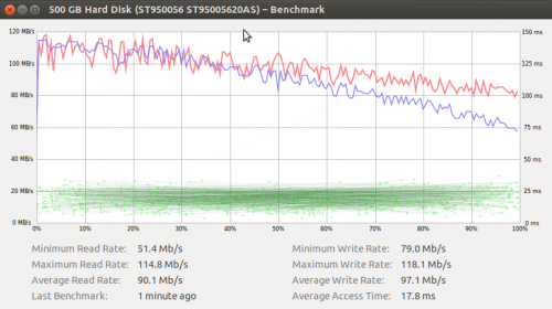
winetricks windowscodecsThe Seagate Momentus XT 500GB hybrid hard drive (4GB SSD, 500GB HDD) is a useful way to speedup system boot and execution. However, on brand new files the speed is the same as a typical hard drive. A USB 3.0 drive adapter shows what the drive could do over a USB 3.0 link, using Disk Utility on Ubuntu.
Average read speed: 90MB/sec. Average write speed: 97MB/sec.
magnetic bottle: pitch angle distribution vs. mirror height equipotential lines -> parallel E-field (Stephen Knight 1970) -> Large scale, dull auroral arc
fine scale arcs assosciated with Farley-Buneman instabilities, GPS scintillation
energy to produce electron-ion pair ionization potential ~ 18 eV takes on average ~ 35 eV
energy deposition physics
single particle motion, 3 adiabatic invariants, Debye length, two fluid vector potential
Alfven wave can couple to whistler mode
Auroral emissions: Bohr model of atom. have to release energy gap between orbitals (work function). Vibrational modes
Ions: closure current electrons: field aligned current
Inertial alfven wave: electron mass matters due to phase speed > speed of light F=ma inertial limit inerital lag – prevents group velocity from exceeding speed of light
λe = c / ωpe electron skin depth confines wave
Auroral emissions:
Björn Gustavsson Ph.D. thesis discusses briefly specifics of four major auroral emission lines.
Thesis on kinetic reactions resulting in auroral emissions.
Auroral width:
Books:
Do NOT do this if you have an encrypted partition, as you’ll lose access to all that data!! reference on forgotten password vis ecryptfs.
mount -o remount,rw /

passwd myusernameWith the spectre of the Positive Train Control mandate looming over small railroads, it’s not only the short-line railroads impacted. Long-distance rural lines can have considerable dark territory. Such railroads may have substantial cost added to their capital budget by PTC. Without radio contact, such railroads have been limited in dark territory to restricted speed 10-25 mph instead of the 49 mph they might otherwise run in dark territory.
The latter option may be much more economically feasible for many rural railroads. This option has not been evaluated for compliance with federal railroad regulations. Railroads in the Rocky Mountains, with vast individual tower coverage areas, have long used DTMF selective calling of dispatch to avoid dispatchers being overwhelmed with constant train chatter.
CONOPS of POTS-linked rural dark territory railroad radio: dispatch has multiple phone lines, all ringing for the same number dedicated to inbound radio calls. Different branches dispatched by distinct dispatchers could obviously have separate phone numbers. The caller ID of the individual interconnect into dispatch identifies the approximate subdivision the train is on (not for legal purposes but for convenience). Cell phones could be used in place of POTS if more economical.
Train to dispatch: train keys up mic, dials dispatch phone number like a standard two-way radio interconnect call. Train engineer uses standard radio message protocol to talk to dispatch, then train hangs up via DTMF. Can use single frequency for network to keep any other trains advised, although dark territory and long distances imply long blocks.
Dispatch to train: dispatch calls phone number of interconnect they believe train is in range of. Train engineer answers via DTMF, uses standard radio protocol to talk. Dispatch hangs up phone, train engineer sends DTMF to close link if phone line hangup not detected.
Besides the typical radio base station tower and antenna, selected with sufficient overlap in 49 mph-desired territory, the Zetron Model 30 is about $600. Cost of power and phone connection trenching might be mitigated by sharing with cellular towers or power utility company where feasible. Naturally, a more advanced interconnect could be used to control and monitor railroad switches and the like, also enhancing railway safety. In regions hauling relatively benign cargo with a single train per day, some in the industry have felt PTC requirements were two stringent. If it’s not too late, some waivers might be obtained for a time at least by using ideas as above, pending compliance with all applicable regulations.