PiRadar
Imagine a dense network of dual-mission HF radars costing $300/node. PiRadar costs 95% less than contemporary radar nodes using the latest COTS SDR technology. Idea, science case, mathematical prototyping and measurements by Juha Vierinen. Red Pitaya and Raspberry Pi prototype and August 2017 Solar Eclipse deployment.
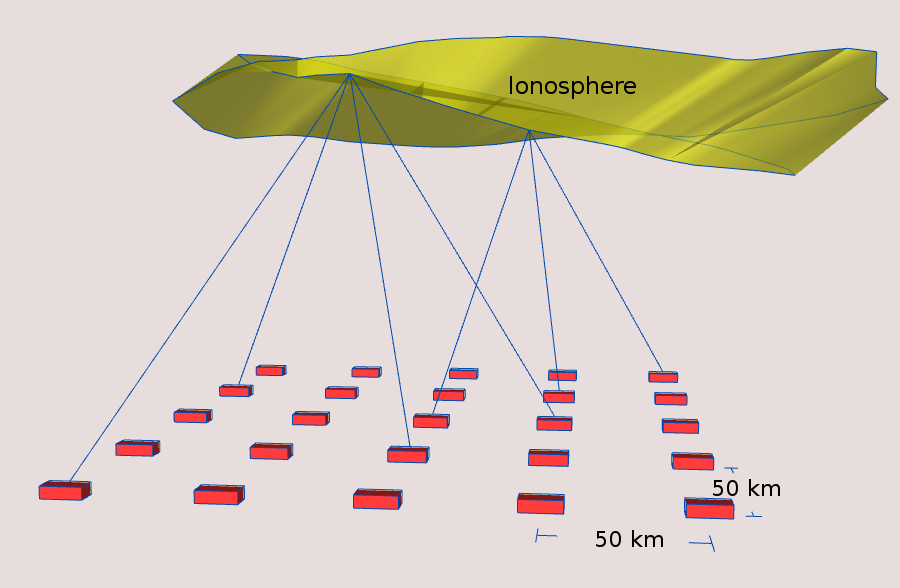
PiRadar nodes in arbitrarily shaped array for ionospheric imaging via pseudonoise HF radar waveforms.
PiRadar simultaneously:
- improving ionospheric models via measurements as an alternative or complement to GNSS TEC measurements
- 4-D imaging of the Earth’s atmosphere/ionosphere
- data relay from isolated sites (e.g. flood alarm, tracking animals)
- Solar storm impact detection and quantification
- Ground-based GPS time-transfer and location service alternative
A simplified system using one antenna for transmit & receive is shown below. Also shown in this figure is a means to inject 1PPS directly into transmit and receive RF streams, in case there is an issue with hardware triggering of DAC or ADC–applicable to general receivers such as RTL-SDR. In this diagram, maximum 20 dBm transmit power is assumed.

PiRadar high-resolution polarization-sensitive HF radar node block diagram.
PiRadar Specifications

PiRadar TX/RX 1PPS pulse injector, single antenna block diagram.
| PiRadar performance metric | value |
|---|---|
| range resolution | 1..25 km |
| data rate | 1..20 kbps |
| transmit power | 1..100 mW |
| transmit bandwidth | 6 kHz..1 MHz |
| node-to-node communication range (skywave) | 50..500 km |
Prior Art: Tiddbit CW HF oblique sounder works in the 2..10 MHz range, transmit power ~ 100 watts.