Enable syntax highlighting:
Before every code block, simply include the language name, for example
```fortran
this even works for gdb.
The color code syntax highlighting on your webpage looks quite striking, and the number of languages covered is very extensive.
Despite the different syntax highlighter modules used by different Jekyll web hosting services, almost every language works with the method above.
Github uses Linguist syntax highlighting for its own service (Issues, README.md, etc.)
Github/Gitlab Pages can use Rouge syntax highlighting via Jekyll _config.yml – specify an allowed syntax highlighter.
At first glance, the two watt transmit power limit across five VHF channels can make MURS seem appealing for long-range license-free radio systems.
In fact, companies such as GoTenna initially chose MURS for their first generation product.
The clear choice for almost all applications is to use 900 MHz modems over MURS 150 MHz modems.
Contact us for a more formal analysis for your application.
MURS data bandwidth:
Freq [MHz]
raw data rate (kbps)
151.82
9600
151.88
9600
151.94
9600
154.57
19200
154.60
19200
At first glance, MURS seems to have a comparable data rate to the $39 one watt 868/900/920 MHz modems, and similar hardware pricing, with seemingly longer range due to 150 MHz vs. 900 MHz frequency.
Interference limits data throughput.
MURS arose in part because of the decades-long abuse of these five VHF itinerant frequencies.
Like the delicensing of 27 MHz CB Radio, the license-free MURS channels arose due to chronic unlicensed use.
Warehouses, hotels, shopping malls, construction sites, etc. use MURS frequencies.
The critical point is that in general MURS modems are stuck on one frequency until reprogrammed.
$14 walkie talkies meanwhile are clogging up the channels.
Cable TV leakage is also a problem at VHF.
Many applications of wireless modems have a latency requirement–how long will an MURS channel be blocked by noise and other users?
The answer comes in using 900 MHz spread-spectrum radio.
900 MHz is also a heavily used frequency band.
The key distinction is this use is spread over as much as 26 MHz (USA).
The one watt transmit power allowed in the USA and numerous other countries, and tens of milliwatts in other countries allows multi-kilometer line-of-sight range, just like 150 MHz radios.
Some 900 MHz modems have a channel list where they hop upon interference, while the high power radios typically employ FHSS.
Having a clear RF channel via FHSS is key to getting even low data bandwidth transmissions through reliably with low latency.
USB host/hubs can use Terminal commands to power on/off USB port remotely.
Linux: apt install gcc make libusb-1.0-0-dev
macOS: brew install gcc libusb make
The uhubctl program allows controlling power for many USB hub models:
git clone https://github.com/mvp/uhubctl

make

./uhubctl -h
Note: key system devices, even built-in laptop keyboards are connected by USB, and you could accidentally poweroff your own laptop keyboard.
So use a little care to identify which hardware port a device is connected to.
Beaglebone Black can power on/off USB ports via devmem2, useful for automatic remote powering on/off of USB peripherals to save energy/heat.
In general devmem2 reads/writes bytes, here the address to control the Beaglebone USB port is known a priori.
apt install devmem2
If apt install devmem2 doesn’t work, you can manually compile:
git clone https://github.com/VCTLabs/devmem2
make
make install
Power on USB port remotely:
devmem2 0x47401c60 b 1
This powered up my Wifi dongle.
I measured 0 V on the USB host port before issuing this command, and measured 5 V after the command.
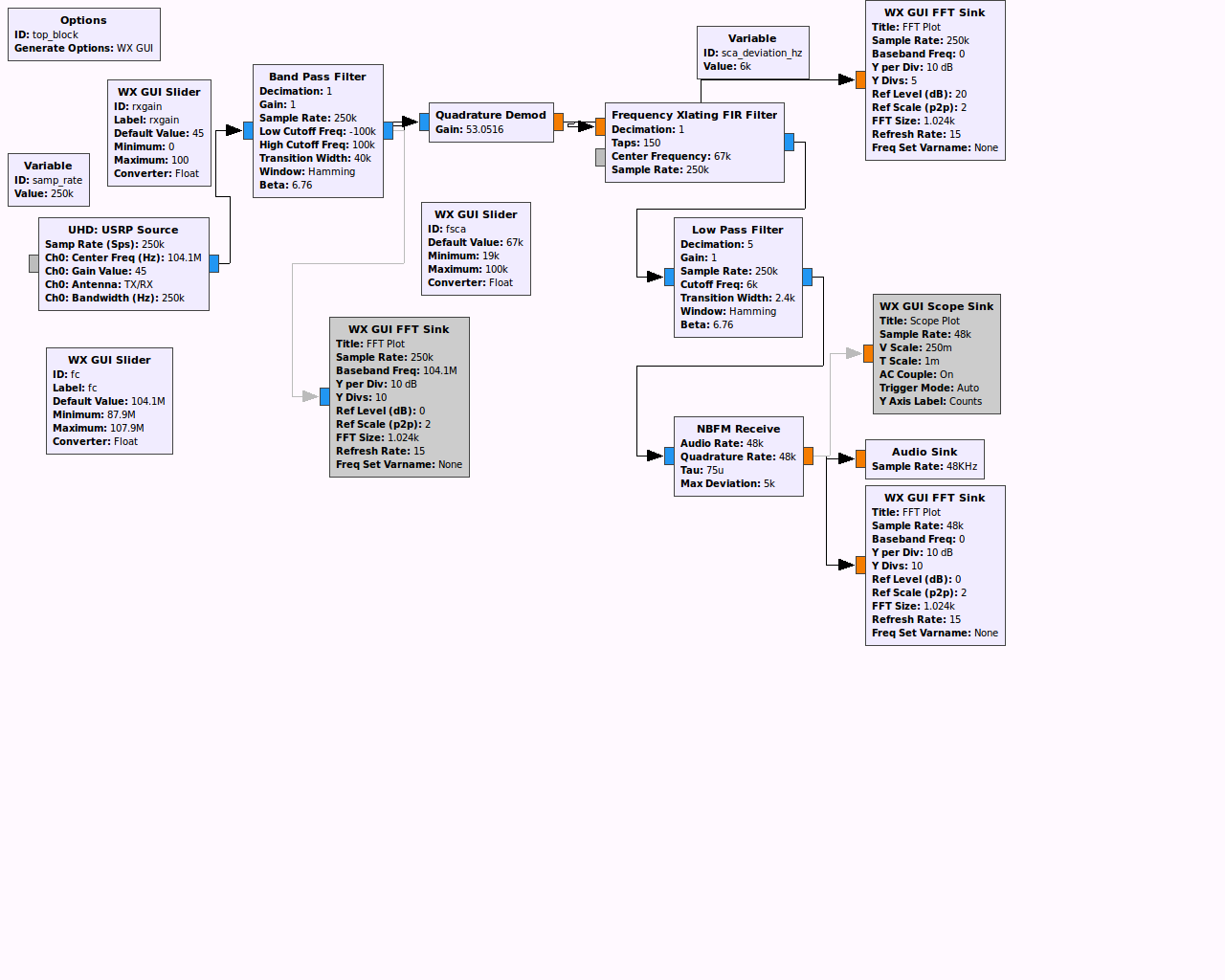
Consider the baseband FM diagram below.
Do not confuse the abscissa with RF spectrum–this is baseband spectrum that is FM modulated before being transmitted on air.
Unfortunately even some technically-oriented websites get this basic and critical fact wrong.
Plain monaural broadcast FM as used prior to 1955/1961, and used wisely by some talk stations today instead of stereo to improve geographic coverage area by reduction of multipath interference, is frequency modulated audio from 50 Hz - 15 kHz.
FM multiplexing was employed in the early FM experiments by Armstrong, back to Nov. 1934 to send additional audio channels, faxes, etc. and
SCA became generally legal for broadcasters in 1955.
The April 1961 selection of the GE / Zenith FM stereo system chose a 19 kHz stereo pilot.
19 kHz is high enough above legacy monaural receivers low-pass filter response to not bother listeners.
88-108 MHz receiver, perhaps direct conversion RTL-SDR, assuming 960 ks/s
bandpass filter say ± 180 kHz before FM demodulation, to block adjacent stations while not making too much distortion. Remember the infinite sidebands of FM–don’t just clip to ± 75 kHz, it will sound badly distorted. OK to decimate down to 480 ks/s.
plain FM demodulation (differentiator) – do not use de-emphasis at this point.
frequency translate and low-pass filter SCA carrier e.g. -67 kHz shift, then low-pass filter 10 kHz or so.
FM demodulate this signal with 150 µs de-emphasis and decimate to sound card rate e.g. 48 ks/s
A normal baseband audio signal is emitted, if one was broadcast at this SCA frequency.
When connecting to multiple Windows PCs using
SSH port forwarding,
you might get error:
The host key for localhost has changed
@ WARNING: REMOTE HOST IDENTIFICATION HAS CHANGED! @
IT IS POSSIBLE THAT SOMEONE IS DOING SOMETHING NASTY!
Someone could be eavesdropping on you right now (man-in-the-middle attack)!
It is also possible that a host key has just been changed.
Consider the security implications of option:
/cert-ignore
option in the freerdp command to bypass this error message.
Since the SSH server and RDP are both on the same Windows PC, the man-in-the-middle check may be somewhat less likely to be needed.
pathlib
is an object-oriented, Python standard library way to handle paths and filenames vs. “dumb” strings.
pathlib.Path() replaces most cumbersome code from os.path and glob.glob.
pathlib is standard library and supported throughout Python natively,
as well as in SciPy, Numpy, et al.
Eliminate messy os.path.join():
filename = pathlib.Path('mydir/a/b') / 'myfile'
Benchmark: pathlib is very efficient, for example with Python 3.6.2 and Ipython 6.1.0:
%timeit Path('~')
2.46 µs ±24.5 ns per loop (mean ± std. dev. of 7 runs, 100000 loops each)
%timeit Path('~').expanduser()
7.35 µs ±7.13 ns per loop (mean ± std. dev. of 7 runs, 100000 loops each)
Matlab
array size limit
attempts to stop the user from creating individual arrays that dig into swap memory.
Using swap memory is normally undesirable for data computations because the swap memory can be several orders of magnitude slower than RAM.
However, Matlab doesn’t check the total size of all arrays in the workspace, so the user must be mindful of
memory management
as in any programming language or data processing task.
The matlab-stdlib
ram_free
function tells the physical free RAM in bytes across operating systems for Matlab or GNU Octave.
If we assume the legacy incandescent lighting was 15 Watts each, that would be 32.9 kW of lighting on one carousel!
I think the incandescent lighting consumed more than 7 watts/light because that’s what old night lights consumed.
In any case, about 20 - 30 kW seems a reasonable estimate.
LED replacement for the carousel lighting would use about 10% of incandescent power, so nowadays that’s still 2-3 kW – more than an electric oven!
If we assume a 10 horsepower motor, that would be roughly 60 amps at 230 Vac single phase, for about 14 kW motor power.
So, an LED-retrofitted carousel might draw about 2 kW sitting still, and 16 kW while spinning.
If we assume 3 hours/day of lighted operation, and 6 hours/day spinning and $0.10/kW electric rate, then the electricity cost to run the carousel is estimated at.
(3 * 2 + 6 * 14) * 0.1 = $9.00 / day with LED lighting
(3 * 20 + 6 * 14) * 0.1 = $14.40 / day with incandescent lighting
However, one must consider the considerable labor cost of relamping the carousel.
Relamping labor is one of the considerable cost savings for commercial LED light upgrades.
Consider the cost of relamping on an incandescent Ferris wheel!
Two-way radio: Canobie Lake Park uses VHF (150 MHz) Motorola CP series portables.
GMRS repeaters on 462.550 and 462.575 (not park-related) were audible.
Because of the rural location and spread out nature of the park, simplex (direct) FRS/GMRS radios work well.
Canobie Lake Park’s maintenance of equipment made before the World Wars is impressive.
Several pieces were made by W.F. Mangels Co., of Coney Island, NY.
Running complicated Windows applications on Linux using WINE requires separate WINEPREFIX.
Each WINEPREFIX has unique Windows configuration, without disturbing the setup of other Windows programs on Linux.
This example is for Irfanview, a highly-useful image Windows viewer/editor that runs well on Linux.
Make the new wineprefix. You would make any special configuration in the GUI that pops up.
WINEPREFIX=~/.wine_irfanview winecfg
Install the winetricks prerequisites for your program. Here, Irfanview requires mfc42.